 5-Axis Process Blueprint
Access Conflicts In Multiaxis Machining Map
Resolving spatial access conflicts in 5-axis and 3+2 machining requires balancing rotary reach against stock envelope evolution. When deep cavities or angled bores are machined prematurely, the remaining raw stock frequently cuts off line-of-sight clearance for subsequent standard toolholders. This blueprint maps the exact dependency graph needed to prioritize clearance cuts before tight-tolerance multiaxis features.
Request Engineering Review & Strategy Access
Spatial Interference Graph
A comprehensive clearance layout mapping spindle head rotation, workpiece envelope transformations, and critical rotary index angles across consecutive cutting cycles.
Dynamic Clearance Priority
Calculated sequence logic that clears interference walls before short-reach tooling enters narrow undercut pockets or multi-angle coordinate holes.
Multiaxis CAM Programmers
Tailored for 5-axis machinists, Mastercam programmers, and manufacturing engineers producing aerospace brackets, impellers, and complex manifold housings.
Experiencing spindle interference on angled holes?
Submit your part geometry and tool assembly clearance constraints for a dedicated multiaxis sequence diagnosis.
The Physics and Geometry of Multiaxis Access Conflicts
In multiaxis CNC milling, tool access is never static. As cutters carve through initial stock, they either create room for subsequent tool assemblies or preserve stock walls that later block the spindle head during rotary indexing. When an angled cross-hole or an undercut pocket is scheduled too early, programmers often discover that the workpiece fixture or adjacent tall bosses prevent the toolholder from achieving the required tilt angle without severe interference.
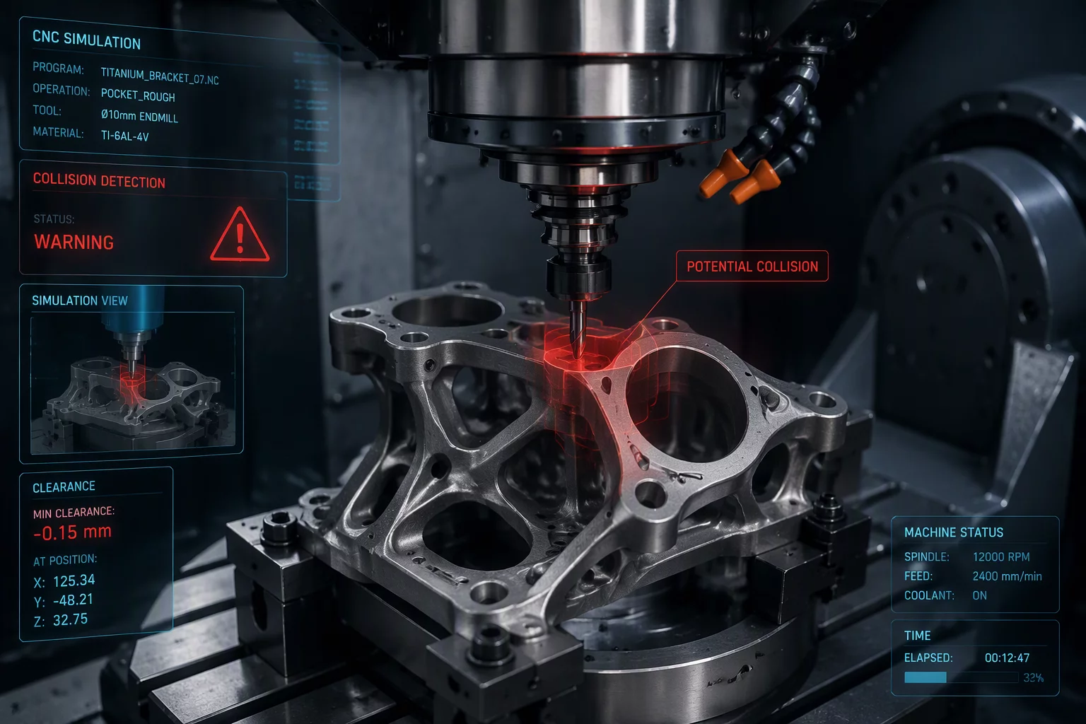
The solution lies in mapping feature dependencies based on volumetric clearance rather than tool diameters alone. By isolating primary clearance envelopes, roughing surrounding bulkheads, and sequencing operations so that line-of-sight access expands rather than constricts, CNC programmers can utilize shorter, more rigid tools while completely eliminating the risk of spindle collisions during compound table tilts.
What This Feature Order Blueprint Delivers
- Rotary tilt vector mapping specifying safe angular limits (A/B and C axes) for deep-cavity entry.
- Volumetric stock-state timeline preventing premature machining of high-aspect-ratio features.
- Tool assembly gauge-length recommendations calculated for minimum deflection and zero holder contact.
- Mastercam 2026 multiaxis toolpath reordering guide optimized with GPU-accelerated collision simulation.
Multiaxis Clearance & Sequence Specifications
Standard engineering parameters and sequencing rules applied when resolving toolholder-to-workpiece clearance conflicts on 5-axis machining centers.
| Parameter | Engineering Value | CAM Rule Context |
|---|---|---|
| Clearance Safety Zone | 2.5 mm – 5.0 mm | Minimum distance maintained between toolholder gauge cone and in-process stock boundary. |
| Rotary Index Reorder Threshold | > 35° Spindle Tilt | Triggers mandatory volumetric pocket clearing prior to indexing secondary compound angles. |
| Tool Length-to-Diameter (L/D) | ≤ 4:1 Ratio Target | Achieved by clearing interference stock first rather than extending tool overhang. |
| Simulation Architecture | GPU-Accelerated Voxel | Full machine kinematic simulation validating dynamic fixture and trunnion clearance. |
Implementation Checklist for Multiaxis Workflows
Validate Volumetric Envelope Before Tool Assignment
Inspect the stock model at every intermediate step. Confirm whether clearing surrounding bulk material first allows a standard holder to reach angled features before resorting to extended arbor toolpaths.
Simulate Full Kinematic Machine Swiveling
Verify toolholder-to-trunnion clearances under true 5-axis simultaneous motion. Reorder tilt sequences if table rotation vectors sweep uncomfortably close to fixture clamps.
Complementary Feature Order Blueprints