 Active CAM Case
Sequence A Toolpath Grouping Architecture
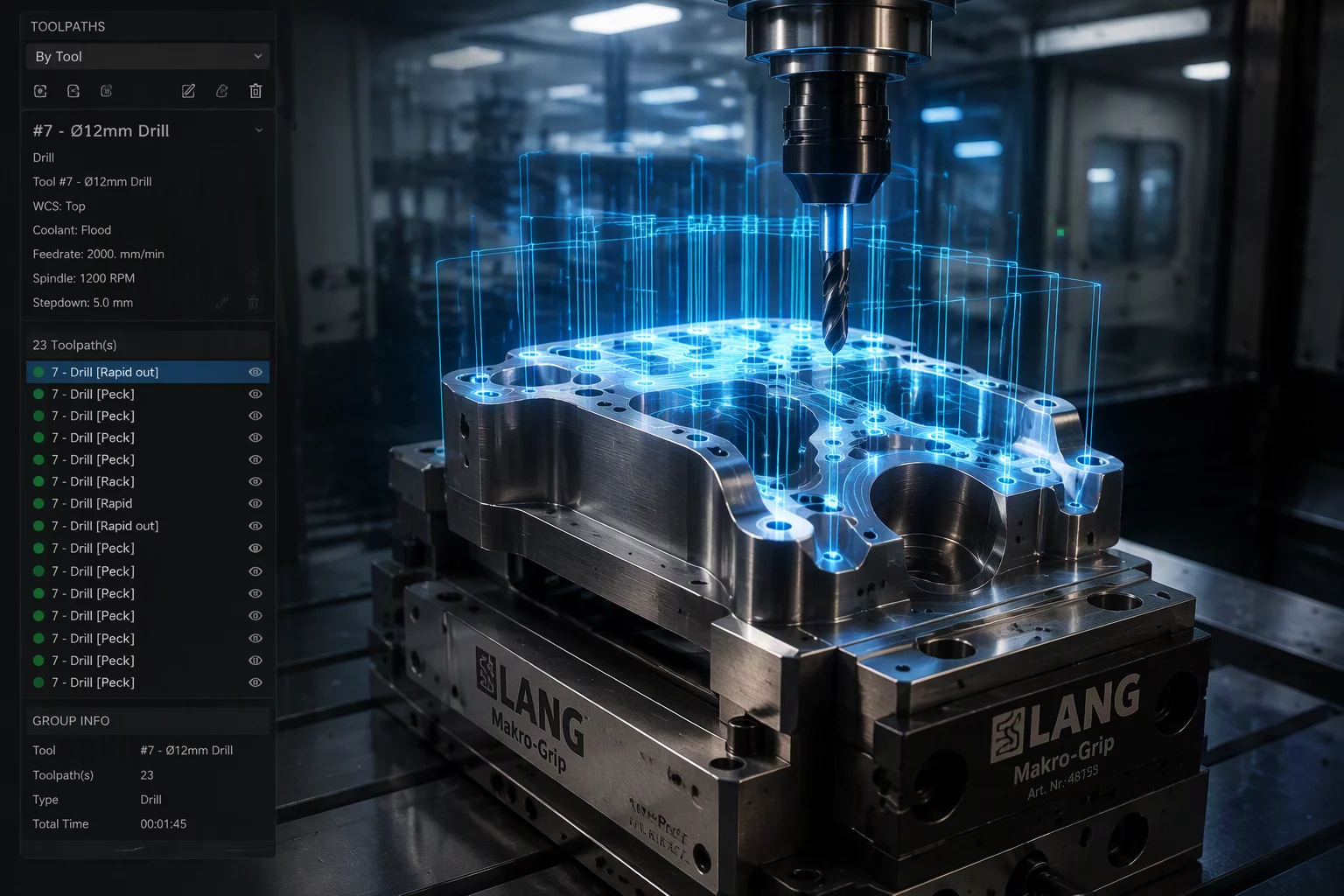
Systematic sequencing protocol optimizing CNC spindle utilization by clustering geometric feature toolpaths around dedicated cutting tools before indexing.
Inquire About Sequence Consultation
Toolpath Consolidation
Clusters all roughing, facing, and profiling operations under one cutter across all accessible part zones before triggering a tool swap.
Cycle Time Minimization
Cuts tool changer cycling and mechanical spindle deceleration overhead by up to 35% on parts with distributed hole and pocket patterns.
High-Volume Milling
Engineered for production CNC programming where rigid fixturing and stable coolant dissipation permit long continuous tool duty cycles.
Optimize Your Machining Operation Tree
Connect with our CAM programming specialists to diagnose feature dependencies and streamline cycle times.
Strategic Toolpath Grouping in Multi-Feature CAM Workflows
Group By Tool represents an operational philosophy that prioritizes machine kinematics over local feature completion. In traditional machining workflows, a programmer might finish an individual pocket entirely—roughing, side-milling, and bottom-finishing—before traversing to an adjacent cavity. Under Sequence A, the CAM tree delegates all roughing routines across the entire component to a single dynamic milling tool. Only after every pocket, boss clearance, and step profile accessible to that diameter is cleared does the automated changer load the subsequent tool assembly. This approach directly tackles non-cutting time, which accounts for up to 40% of cycle duration on complex prismatic components.
While grouping by tool produces undeniable cycle-time advantages, it introduces critical physical risks if downstream dependencies are ignored. Removing bulk material unevenly across a prismatic billet releases internal rolling stresses, which can cause micro-deflection in thin-walled ribs before finishing tools ever make contact. Furthermore, drilling pilot holes or finishing delicate chamfers on unsupported webs demands precise clamping force monitoring. In Mastercam programming, implementing Sequence A requires structuring stock models between tool groups and verifying that roughing cusps do not cause toolholder shank collisions during deep-cavity entry.
Case Study Deliverables & Verification Data
- Step-by-step Mastercam toolpath organization matrix for 3-axis and 3+2 indexed machining
- Kinematic tool change overhead calculations comparing tool-grouped and feature-grouped workflows
- Residual stress risk assessment protocol for thin-wall components under prolonged tool engagement
- Automated collision avoidance and toolholder shank clearance checkpoints for deep pockets
Technical Parameters & Machining Standards
Operational tolerances, kinematic guidelines, and CAM configuration thresholds established for Sequence A validation.
| Parameter | Engineering Value | CAM Rule Context |
|---|---|---|
| Average Tool Change Time | 4.8 to 8.2 seconds | Kinematic index duration saved per consolidated feature operation |
| Stock Model Update Frequency | Post-Tool Group | Inter-stage verification mesh generated after each primary cutter completion |
| Thermal Drift Compensation | ±0.005 mm | Threshold for warm spindle elongation during extended single-tool passes |
| Recommended Batch Scope | Production > 25 units | Optimal volume threshold where tool-change savings offset sequencing verification |
Implementation Checklist & Best Practices
Establish Primary Datum Stability
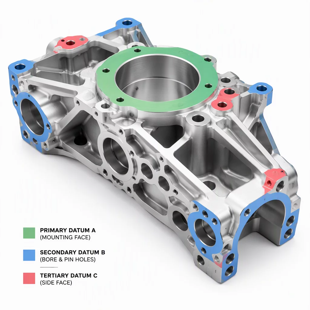
Machine locating dowel bores and clamping reference pads in the initial operation group before high-volume material removal introduces thermal variations.
Validate Rest Material Envelopes
Verify toolholder clearances against intermediate stock models to prevent high-speed shank engagement with unroughed cusps in nested pockets.
Complementary Feature Sequencing Blueprints