
Machine the Reference Before the Dependent Feature
Establishing primary datums and reference faces prevents cumulative geometric errors when cutting subordinate features.
Study cases where holes, pockets, bosses, faces, and reference surfaces depend on machining sequence.
Creates reference plane A before any blind bore coordinate definition.
Clears 38mm core bulk to create toolholder access for bottom drills.
Drilled strictly after pocket floor opening to prevent tool shank deflection.
Referenced from internal bore axis drilled in previous operation.
Finished geometric positioning confirmed without tool re-indexing error.
Which feature should exist before another feature can be machined reliably?
Systematic feature ordering prevents tooling gouges, minimizes fixture turnover, and stabilizes datum integrity across complex multi-axis CAM workflows.
A common failure mode in CAM setups is referencing secondary operations against unfinished stock. High-precision manufacturing requires milling primary datum faces, locating bores, and reference pads first to ensure all subsequent positional tolerances remain intact.
Face mill primary base and edge indicators to calibrate true coordinate alignment.
Rough primary faces before precision boring to release internal material tensions.

Analyzing how aggressive volumetric clearing alters material engagement for subsequent semi-finishing operations in Mastercam 2026.
Mastercam does not automatically define an absolute optimum. In precision CAM workflows, order selection is a deliberate trade-off between spindle cycle time, datum retention, and cutter interference.
Runs center drill across all six holes consecutively, followed by the primary drill toolpath, and concludes with boring the three deep cavities. Dramatically trims tool changes while postponing datum locking.
Completely finishes the three 12mm holes first with spot, drill, and chamfer passes. Once finished, recalibrates spindle feeds and pecking clears to execute the three 38mm deep chambers.
Synchronizes drilling directly with reference pocket milling and secondary datums. Critical locator holes are machined while clamping tension is freshest, locking positional precision.
Compare core mechanical implications across all three pathways before generating G-code.
| Trade-off Factor | Sequence A | Sequence B | Sequence C |
|---|---|---|---|
| Tool Changes | 2 (Lowest) | 6 (Highest) | 4 (Balanced) |
| Z-Access Clearance | Uniform | Staged | Safe Clamped |
| Datum Continuity | Fragile | Moderate | True Position |
| Downstream Risk | High Drift | Low Deflection | Isolated |
When machining parts with varied hole depths, grouping strictly by tool cuts seconds off cycle time but exposes tight counterbores to clamping shift. Choose by coordinate criticality.
Explore proven routing blueprints and geometric dependency orders engineered to eliminate tool access interferences and maintain strict datum integrity.
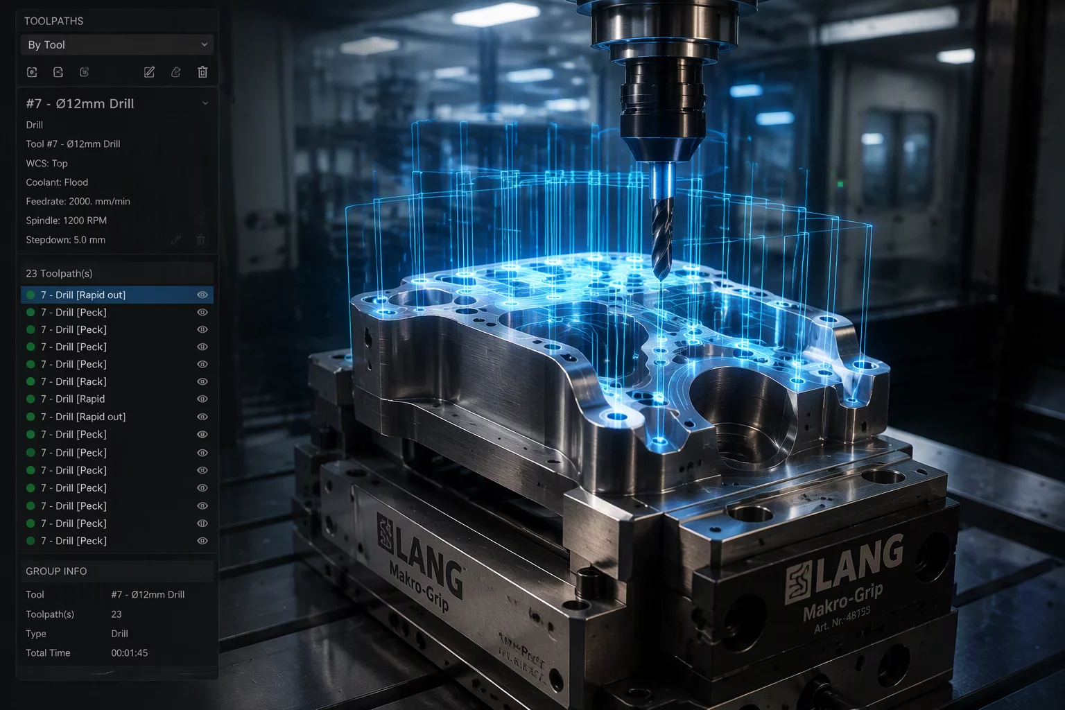
Minimizes tool change overhead by machining all identical-diameter bores before swapping cutters.
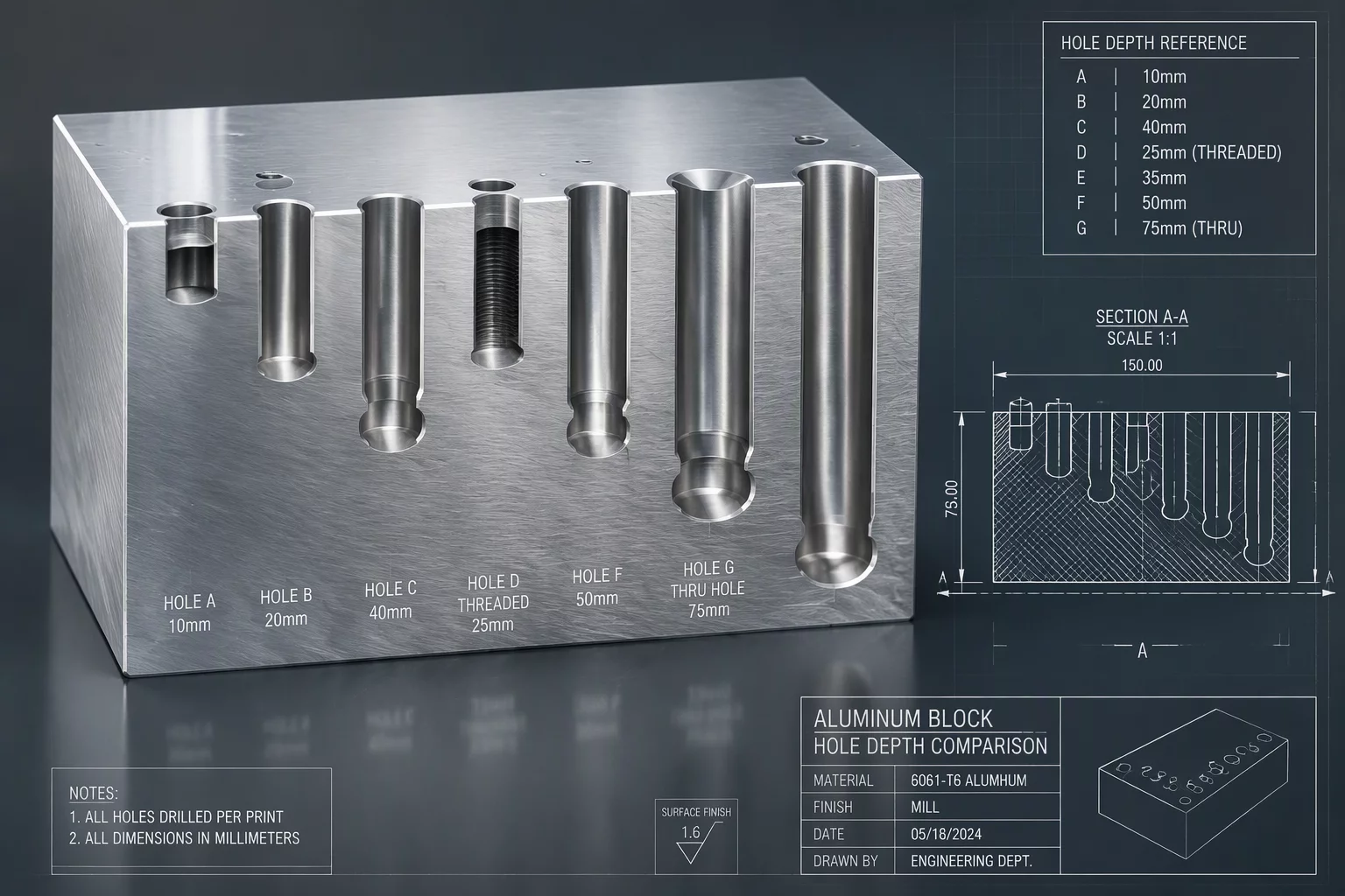
Structures step depths sequentially to ensure workpiece rigidity and prevent thin-wall vibration.
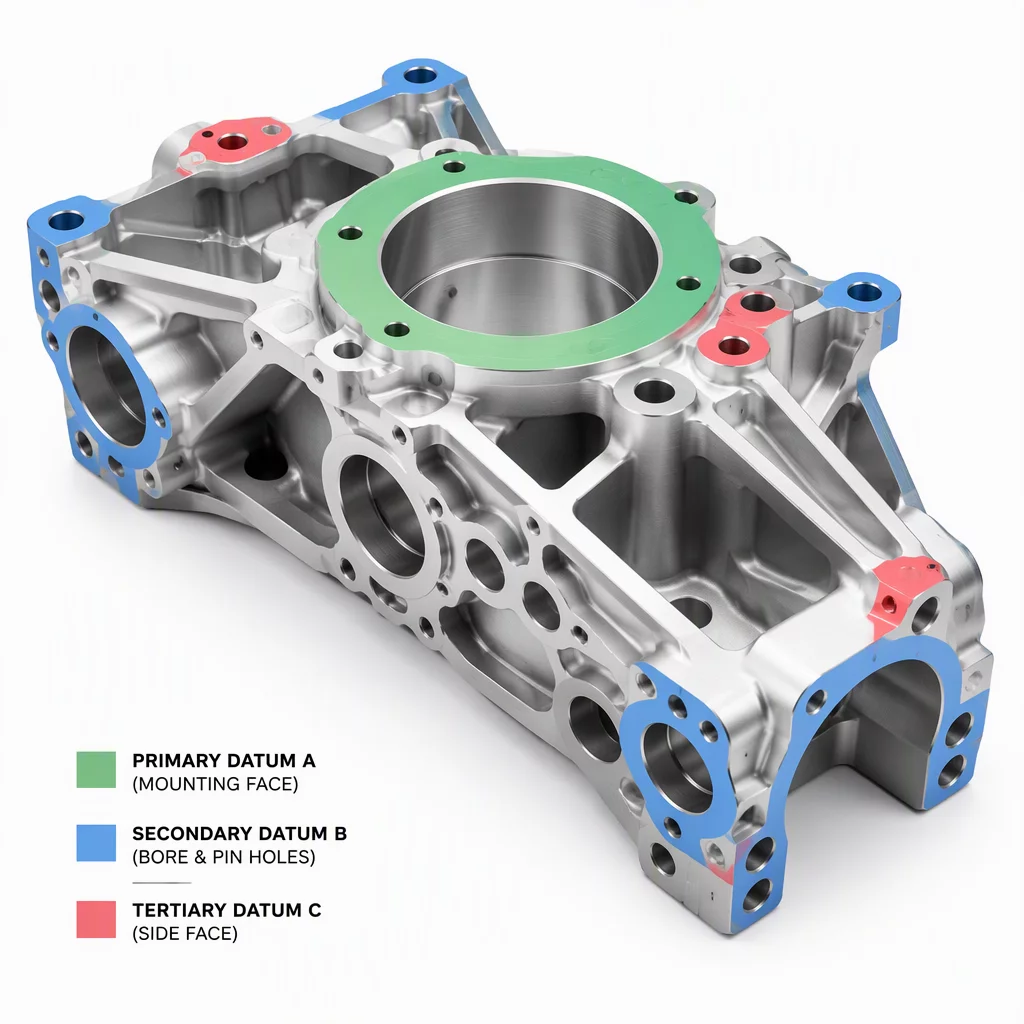
Maps relational datums to lock coordinate alignment across multi-station vice transfers.
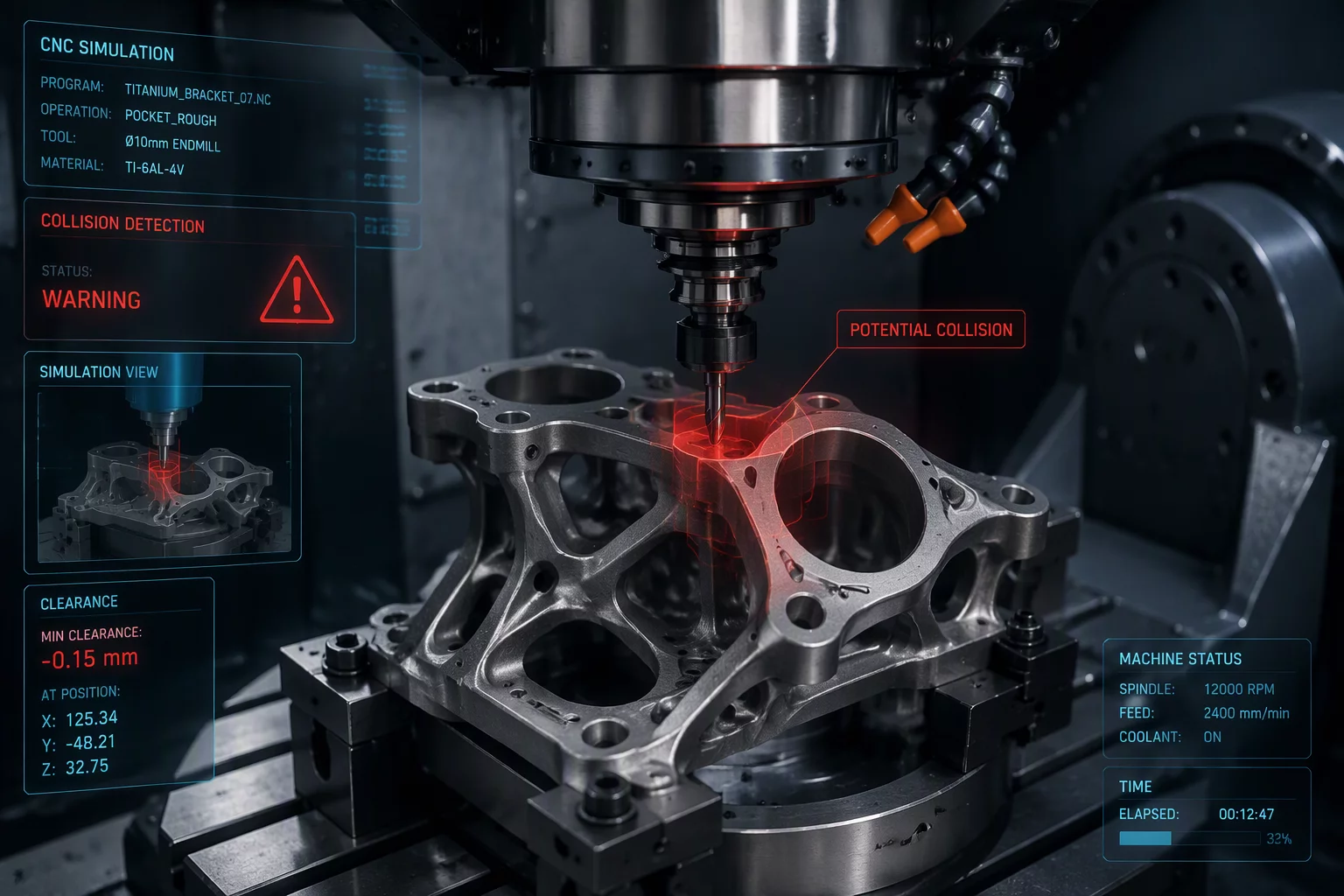
Identifies toolholder reach limits and evaluates clearance paths before finalizing spindle vectors.
Practical methodologies for resolving feature order conflicts, datum dependencies, and multi-axis clearance limits.
Establishing primary datums and reference faces prevents cumulative geometric errors when cutting subordinate features.
Grouping visually identical holes into a single toolpath can jeopardize precision when depth tolerances and bore finishes differ.
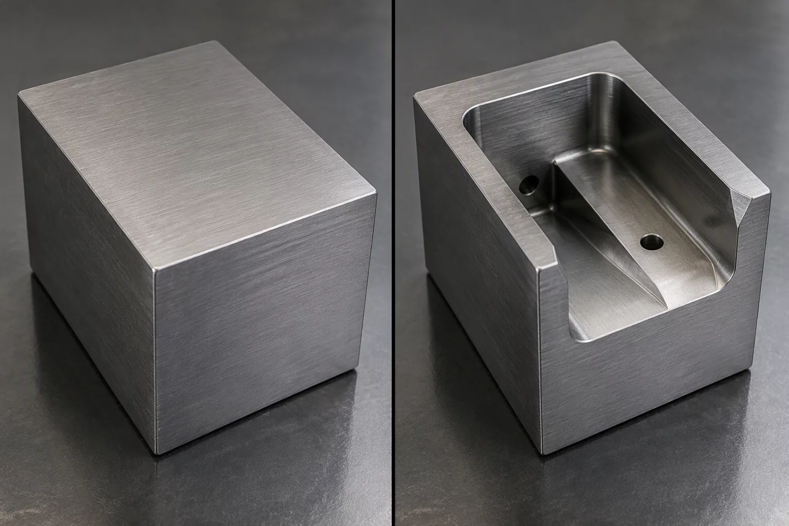
Clearing deep pockets alters the clearance envelope for nearby drilled holes, shifting entry angles and tool reach constraints.
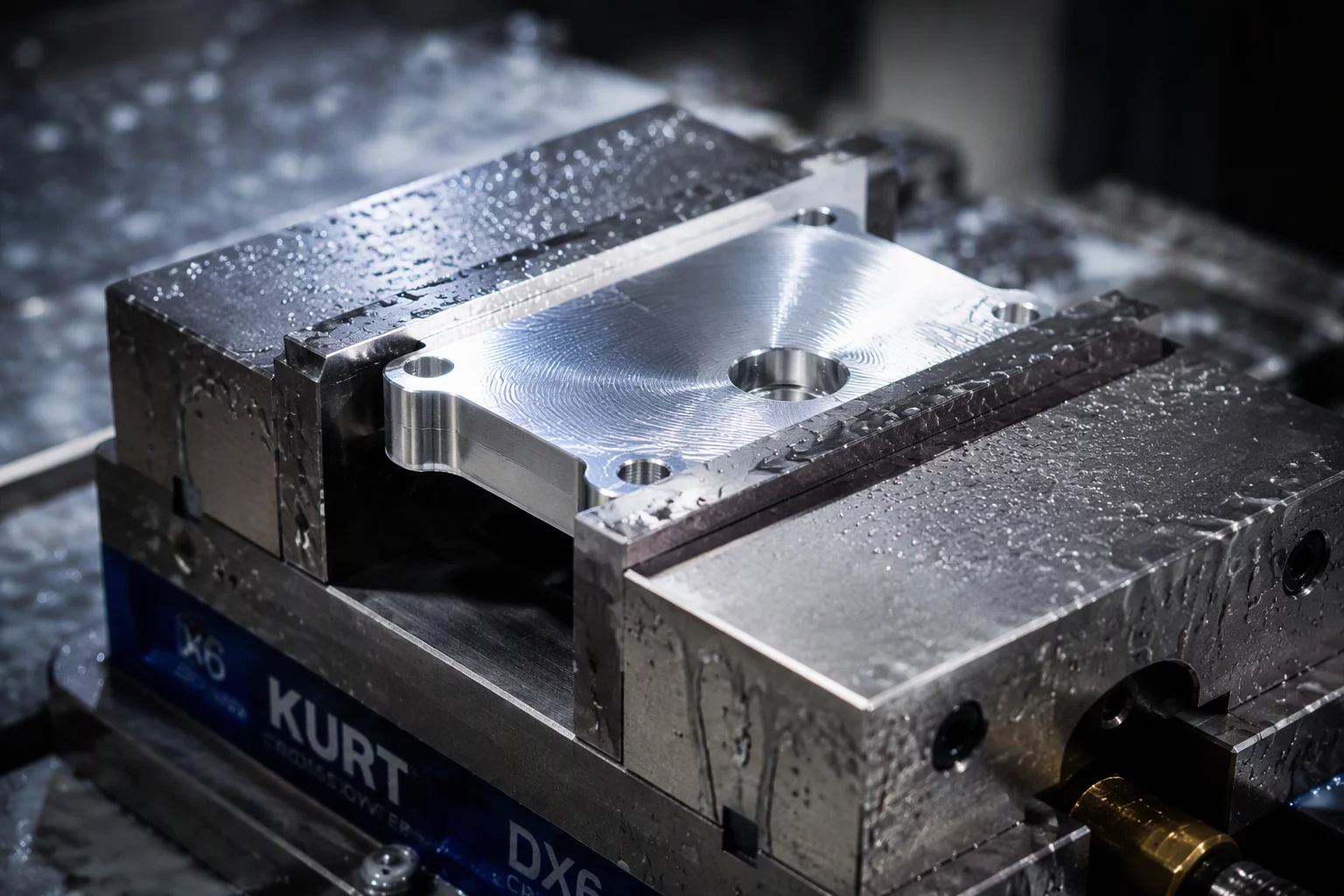
Transitioning a freshly milled face into the locator for subsequent operations requires verifying clamping pressure and runout.
Use this technical audit checklist before awarding any CNC machining or Mastercam programming contract. Even if you partner elsewhere, these verification standards protect your parts from costly sequencing defects.
Why this matters: Generating toolpaths directly from CAD model trees without checking sequence hierarchy leads to premature material removal, wall chattering, and unreachable pockets.
“We program directly off the SolidWorks tree order and let the machine operator adjust depths manually.”
“We construct a formal Feature Order Map to confirm critical reference planes before pocket roughing or finishing.”
Why this matters: Repositioning a part onto a newly machined surface without compensating for clamp deformation or tool pressure introduces geometric tolerance stack-ups.
“We flip the part into standard smooth vice jaws and assume the origin zero shift handles alignment.”
“We isolate datum preparation passes, verify flatness tolerances, and program dedicated soft-jaw interfaces.”
Why this matters: Simulating against the finished part geometry conceals gouges where intermediate stock remains, resulting in catastrophic shank rubbing or toolholder crashes.
“Standard wireframe toolpath simulation shows our clearances well enough before cycling the machine.”
“We update Mastercam stock models after every single operation group to simulate exact holder and stock envelopes.”
Why this matters: Bundling five holes of identical size into one canned cycle to minimize tool changes causes scrap when one hole is a press-fit dowel datum and the others are loose clearance taps.
“We select all matching diameters across the body simultaneously to keep overall run cycle time lowest.”
“We split features by GD&T intent, isolating critical dowel coordinate cycles with dedicated reaming passes.”
Why this matters: Without transparent sequence documentation, revisions cannot be audited, and your team is trapped when minor engineering design changes occur.
“We only export raw G-code files. Documenting individual sequence trade-offs is proprietary.”
“We export full tool list summaries, setup orientation matrices, and operation dependency maps with all deliverables.”
Precision CAM programming, machine order optimization, and Mastercam toolpath architecture delivered seamlessly across international manufacturing facilities.
Synchronous engineering handoffs from 07:00 EST to 18:00 PST, supporting tier-1 aerospace and medical machine shops across the US and Canada.
End-to-end encrypted repositories with strict air-gapped staging for solid model geometry, tooling libraries, and proprietary machine kinematics.
Remote GPU acceleration simulates complex multiaxis operations and verifies dynamic roughing sequences without machine idle time.
Active engineering consultation covering 08:00 CET to 17:30 GMT for tooling builders and precision suppliers in Germany, the UK, Switzerland, and Scandinavia.
Strict adherence to ISO and DIN cutting standards, high-feed dynamic parameters, and comprehensive 5-axis collision checking.
Synchronized spindle handoffs and multi-stream sequence analysis structured for DMG Mori, Mazak, and Hermle manufacturing centers.
Take advantage of time zone offsets: submit your part geometry at the close of your shift and receive verified Mastercam operations before morning setups.
Optimized for contract manufacturers handling repetitive setup changes, minimizing tool reload cycles and stabilizing machine datums.
Fast-track sequence diagnosis for urgent tooling revisions and complex multiaxis prototype setups with high geometrical tolerances.
No physical on-site visits are necessary. Our structured remote methodology guarantees complete alignment with your CNC equipment, tooling catalogs, and machining constraints.
You upload STEP, Parasolid, or native Mastercam models alongside your machine model, spindle speed envelope, and current fixture setup.
We construct the Feature Order Map, eliminate access conflicts, optimize roughing passes, and verify complete tool clearance via accelerated GPU simulation.
Receive verified Mastercam toolpath trees, setup documentation, G-code post recommendations, and a detailed video sequence breakdown.
Eliminate project ambiguity before CAM engineering begins. Review the exact engineering items included in our Mastercam sequence order audits alongside distinct boundaries.
Comprehensive virtual diagnostics, dependency planning, and verified tool access models executed directly in Mastercam.
Explicit non-deliverables requiring separate specialized machining contracts, tooling purchase, or internal shop facilities.
Arbitrary sequence planning in CAM frequently generates hidden tool collisions, unrecoverable datum shifts, and expensive machine downtime. Discover what typically goes wrong on the shop floor and how systematic sequence mapping eliminates scrap.
Programmers often bundle all drill cycles first to save tool changes. When primary mating faces are machined downstream, stress relief shifts coordinate locations, forcing positional runout beyond true position tolerances.
Roughing and finish boring coordinate holes from raw stock faces prior to establishing true planar references.
Machine primary datum surfaces first, establish work coordinates, then execute finish boring with stable rest-material.
Cutting deep central pockets changes clearance envelopes for nearby angled holes. When tools retract assuming full solid block envelope instead of updated dynamic in-process stock, holders scrape remaining wall stock.
Generating drill lead-ins using static initial boundary files without linking dynamic stock updates between operations.
Map feature dependencies so roughing updates stock models progressively before triggering deep clearance routines.
Flipping components between fixtures without verifying whether subsequent clamping surfaces carry sufficient surface area produces workpiece deflection, chatter marks, and cumulative dimensional errors across multiple axes.
Machining secondary features on unsupported thin ribs after removing clamping stock in setup 1.
Balance structural rigidity by postponing aggressive roughing until opposed structural datums are locked securely.
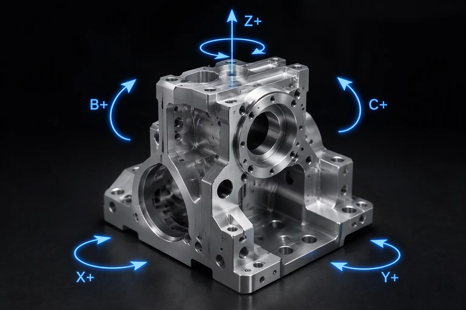
Review empirical data from actual machine setups illustrating how re-orienting five-axis sequence priorities avoids datum drift and minimizes fixture setup swaps by 35%.