 Production Reference
Multi-Side Part Setup Tradeoffs
When prismatic workpieces present features on four or more faces, CNC programmers confront a fundamental decision: consolidate machining operations into fewer multiaxis indexed setups, or divide them across multiple rigid vise fixtures. This engineering blueprint analyzes the direct tradeoffs between datum stackup tolerances, tool overhang deflection, and setup changeover cycles.
Request Architecture Consultation
Setup Allocation Guide
A comprehensive decision map detailing how cutting forces, geometric tolerances, and rotary axis clearances dictate feature distribution across multiple machine setups.
Tolerance vs Rigidity
Direct evaluation models that compare positional errors caused by multiple manual reclamps against deflection vibrations introduced by long tool extensions in 5-axis indexing.
CAM Leads & Engineers
Engineered for production CNC programmers, toolpath architects, and machine shop planners tasked with optimizing complex parts on 3-axis, 4-axis, or 5-axis machining centers.
Facing compound datum shifts across complex setups?
Consult with our CAM sequence engineers to evaluate Mastercam 2026 setup hierarchies and GPU collision simulations tailored to your machine fleet.
The Core Paradox of Multi-Side Machining Sequences
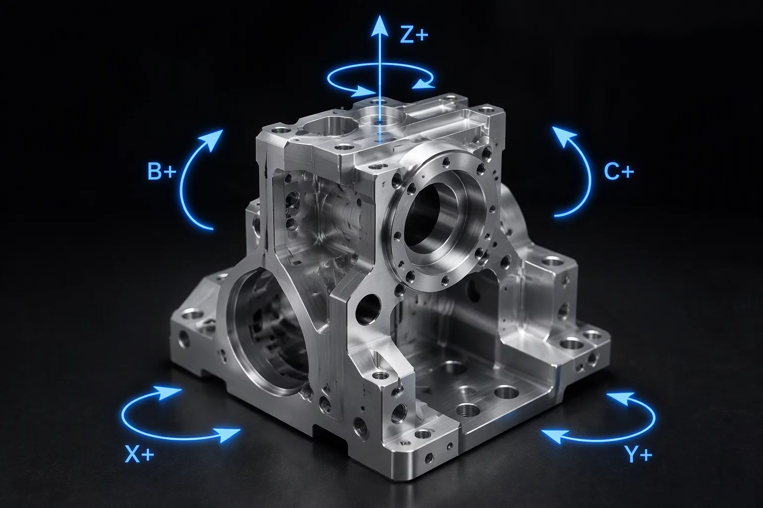
Every multi-side prismatic part presents a battle between geometric datum retention and dynamic machining rigidity. When a workpiece is completed in a single 3+2 rotary setup, geometric relations between perpendicular hole patterns and face datums remain locked within machine encoder precision. However, accessing recessed features from oblique rotary angles demands extended toolholders and long-reach cutters. These slender tooling assemblies severely restrict allowable depth of cut and feed rates due to bending moments and harmonic chatter, turning aggressive dynamic roughing cycles into sluggish finishing-style passes.
Splitting the workpiece into multiple dedicated 3-axis operations resolves the rigidity problem by clamping the stock firmly in low-profile hardened vise jaws right next to the cutting zone, enabling maximum material removal rates with short, stubby tools. Yet each mechanical transfer introduces cumulative error: chucking repeatability, micro-swarf entrapment, jaw deflection under hydraulic pressure, and datum pickup deviations. In Mastercam 2026, leveraging automated stock model transfers and GPU-accelerated collision simulation allows programmers to quantify these exact tradeoffs before committing raw billet to the machining floor, balancing overall cycle time against scrap risk.
Key Decision Criteria in Setup Sequencing
- Datum qualification precedence: always machine primary reference faces and locator holes in Setup 1 before releasing stock stresses.
- Tool length-to-diameter threshold: limit indexed reach to 4:1 L/D for roughing passes; transition to secondary setups when exceeding 6:1.
- Stock balance and internal stress management: execute balanced roughing cuts on opposing faces before finishing critical bore diameters.
- Rotary clearance boundary verification: validate table tilt and toolholder body clearance in Mastercam 2026 GPU simulation.
Engineering Evaluation Matrix
Quantitative comparison between consolidated 5-axis multiaxis indexing and discrete multi-vise 3-axis setups:
| Parameter | Engineering Value | CAM Rule Context |
|---|---|---|
| True Position Repeatability | ±0.0003 in (Single) vs ±0.0015 in (Multi-Op) | Multi-vise transfers incur cumulative fixture and probe error stackup across datum re-alignments. |
| Tool Overhang Ratio | Up to 8:1 (Indexed) vs 3:1 (Dedicated Vise) | Short tooling in dedicated setups allows higher chiploads and prevents dynamic vibration chatter. |
| Non-Cutting Cycle Time | Reduced by 45–60% in Indexing | Consolidating into a single multiaxis cycle eliminates manual part handling and indicator dial-in. |
| Simulation Verification Tier | Full Machine Kinematics + GPU Mesh | Mastercam 2026 Copilot and GPU collision engines flag trunnion and toolholder envelope interferences. |
Critical Implementation Rules
Lock the Primary Datum Plane
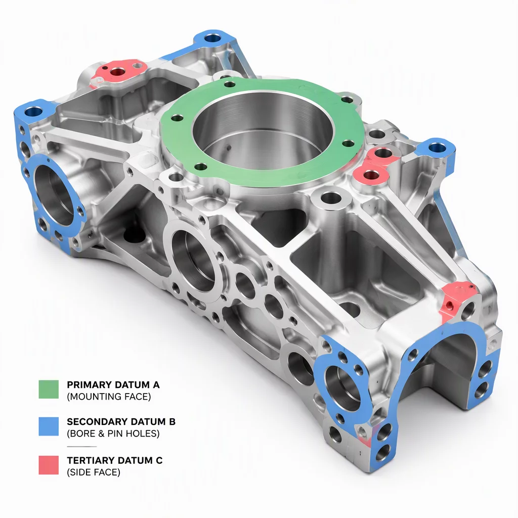
Always machine and qualify the primary locating face and reference dowel bores in Setup 1 before initiating any heavy roughing on opposing faces. Establishing this reference foundation first ensures consistent datum tracking across all subsequent rotary index angles or secondary jaw transfers.
Rough Symmetrically to Minimize Warpage
Distribute bulk roughing passes equally across opposing component sides before applying final finish cuts to any single face. Relieving residual stresses symmetrically prevents internal material tension from bowing the component after it is unbolted from the fixture.
Related Feature Order Blueprints