 Verified CAD/CAM Sequence
Pocket Toolpath Dependency Mapping
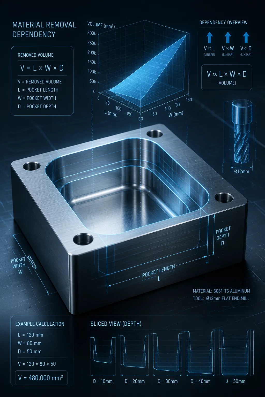
Detailed workflow protocol examining how deep cavity roughing alters residual stock envelopes for internal bosses, intersecting holes, and secondary pocket floors.
Request Technical Implementation Brief
Hierarchical Pocket Topology
Clear pockets from widest top clearance boundaries down to stepped internal cavities, securing chip evacuation and minimizing cutter engagement spikes.
Stock Boundary Propagation
Every dynamic pocket clearing operation recalculates raw stock boundaries before subordinate profiling or finishing passes engage critical walls.
CAM Programmers & Toolmakers
Engineered for CNC machinists and manufacturing engineers programming prismatic pockets, deep cavities, and thin-rib enclosures in Mastercam.
Have Complex Pocket Toolpath Clashes?
Our CAM sequence review evaluates cutter stick-out, radial chip thinning, and fixture collision points across all pocket stages.
The Mechanics of Pocket Dependency Sequencing
When machining intricate pocket assemblies, cutting deeper cavities alters both structural rigidity and geometric accessibility for all adjacent part features. Clearing a deep pocket before machining neighboring through-holes or thin ribs often induces harmonic vibration, wall deflection, and cutter chatter. By mapping pocket toolpaths into a formal dependency matrix, programmers ensure that exterior datum references and bulky surrounding stock remain intact during heavy roughing, only executing finishing passes once residual stresses normalize.
Mastercam 2026 copilot and GPU accelerated simulation calculate tool engagement across dynamic motion passes in real time. Under this protocol, programmers track rest material envelopes from larger diameter roughers down to micro end mills without losing track of fixture clearances. This prevents unexpected plunge collisions into leftover corner material and avoids premature tool wear on high-aspect-ratio cavity corners.
Package Deliverables & Process Map Elements
- Hierarchical pocket roughing flowchart with tool engagement thresholds
- Dynamic pocket boundary stock-model transfer protocols
- Thin-wall pocket sequencing checklist for deflection mitigation
- Mastercam copilot simulation parameter guidelines for pocket corner clearing
Pocket Sequencing Parameter Matrix
Reference values and operational constraints for multi-stage pocket milling sequences.
| Parameter | Engineering Value | CAM Rule Context |
|---|---|---|
| Roughing Stepdown Ratio | Up to 2.5× Tool Diameter | Optimized for radial chip thinning and dynamic motion pocket clearing. |
| Corner Stock Allowance | 0.30 mm – 0.50 mm | Maintains consistent chip load before semi-finish pencil tracing. |
| Wall Deflection Threshold | < 0.015 mm Total Indicator | Dictates alternating depth passes for tall, unsupported thin ribs. |
| Simulation Verification | GPU Accelerated Engine | Validates shank and holder clearances in deep cavity approach moves. |
Execution Guidelines for Multi-Stage Pockets
Verify Stock Model Continuity
Always pass an updated stock model into subsequent rest-roughing operations. Skipping stock model updates causes tools to air-cut or experience abrupt impact loads when entering deep corners.
Balance Residual Wall Support
When pockets share thin separating walls, rough both cavities incrementally rather than completing one entirely. This maintains structural mass and prevents chatter marks on finished faces.
Correlated Sequencing Maps