Transferring Datum Planes Across Sequential Machining Setups
In multi-axis and multi-operation CNC workflows, parts rarely stay clamped in one orientation. Once an initial face is planed and qualified, it transitions from a raw target into the primary contact plane for Op 20. Failing to respect this datum evolution results in cumulative angular deviation and scrapped assemblies.
Datum Evolution Parameters
Key physical parameters dictating how a machined face serves as an operational reference.
| Parameter | Reference Value | Operational Dependency |
|---|---|---|
| Surface Planarity (Flatness) | Within 0.005 mm (0.0002 in) | Mandatory prior to flipping into secondary ground fixture jaws |
| Fixture Clamping Pressure | 14 - 18 Nm Torque | Prevents elastic deflection against the finished datum plane |
| WCS Alignment Origin | G55 Probe Point on Finished Face | Overrides raw stock corner references established in Op 10 |
| Toolpath Clearance Boundary | 5.0 mm Safety Retract Plane | Safeguards against fixture hardware clamping over the datum surface |
| Cumulative Runout Tolerance | < 0.012 mm Total Indicator Reading | Maintains parallelism between opposing datum features |
Executing Datum Surface Transitions
Three rigorous phases to preserve datum fidelity from roughing through second-operation locating.
Qualify the Primary Base Surface
Face-mill the primary datum with a dedicated finishing pass. Always ensure cutting forces do not bow the unsupported raw workpiece.
Locate Against the Finished Face
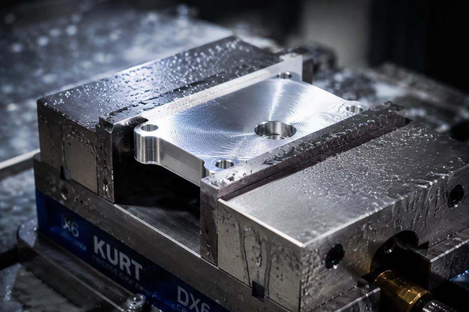
Flip the part and rest the newly qualified plane directly on ground parallels or vacuum chuck beds to fix the Z-height datum solidly.
Re-probe Coordinate Systems
Set your secondary work coordinate system (WCS) directly from the finished surface rather than carrying over unverified stock dimensions.
Quality Control Validation Points
Systematic verification criteria ensuring the new datum functions predictably.
Need Assistance With Complex Machining Sequences?
Explore our comprehensive Operation Analysis series to master feature dependencies, multi-axis reachability, and robust setup ordering.
Sequential Machining Case Studies
Further reading on coordinating tool sequences and reference geometry.