When Clamping Integrity Clashes with Feature Access
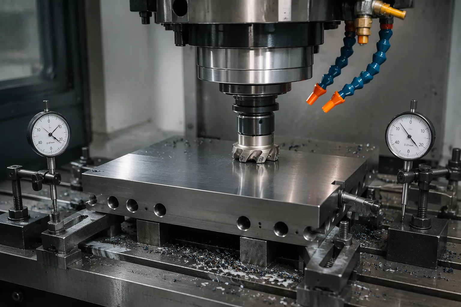
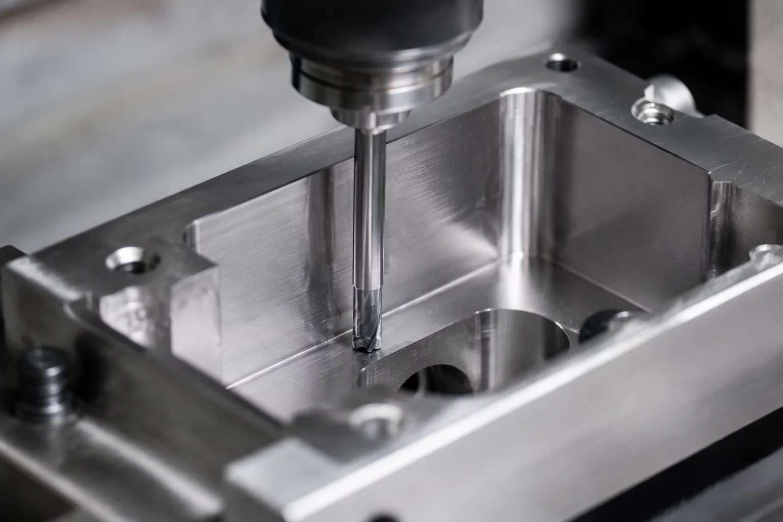
When two distinct geometric features require the exact same physical orientation, machining both in one setup appears optimal on paper. However, holding the part rigidly for heavy pocketing often traps the side clearance required for deep cross-drilling. Alternatively, releasing clamping pressure between roughing and finish boring compromises datum coordinates. This analysis outlines trade-offs between monolithic single-setup fixturing and intentional multi-op staging.
Setup Conflict Matrix & Feasibility Metrics
Quantitative thresholds determining whether to machine competing features simultaneously or divide them into sequenced operations.
| Parameter | Reference Value | Operational Dependency |
|---|---|---|
| Primary Clamping Zone | Vise Jaws on Outer Flange | Blocks 18mm endmill radial entry for side relief pocket |
| Datum Transfer Error | ±0.005 mm max tolerance | Re-clamping requires probe calibration against finished bore |
| Tool Overhang Ratio (L/D) | 6.5:1 reach required | Chatter vibration risks fine bore finish if clamped loosely |
| Wall Thickness Compliance | 2.2 mm remaining floor | Roughing pocket first deforms locating face for subsequent drilling |
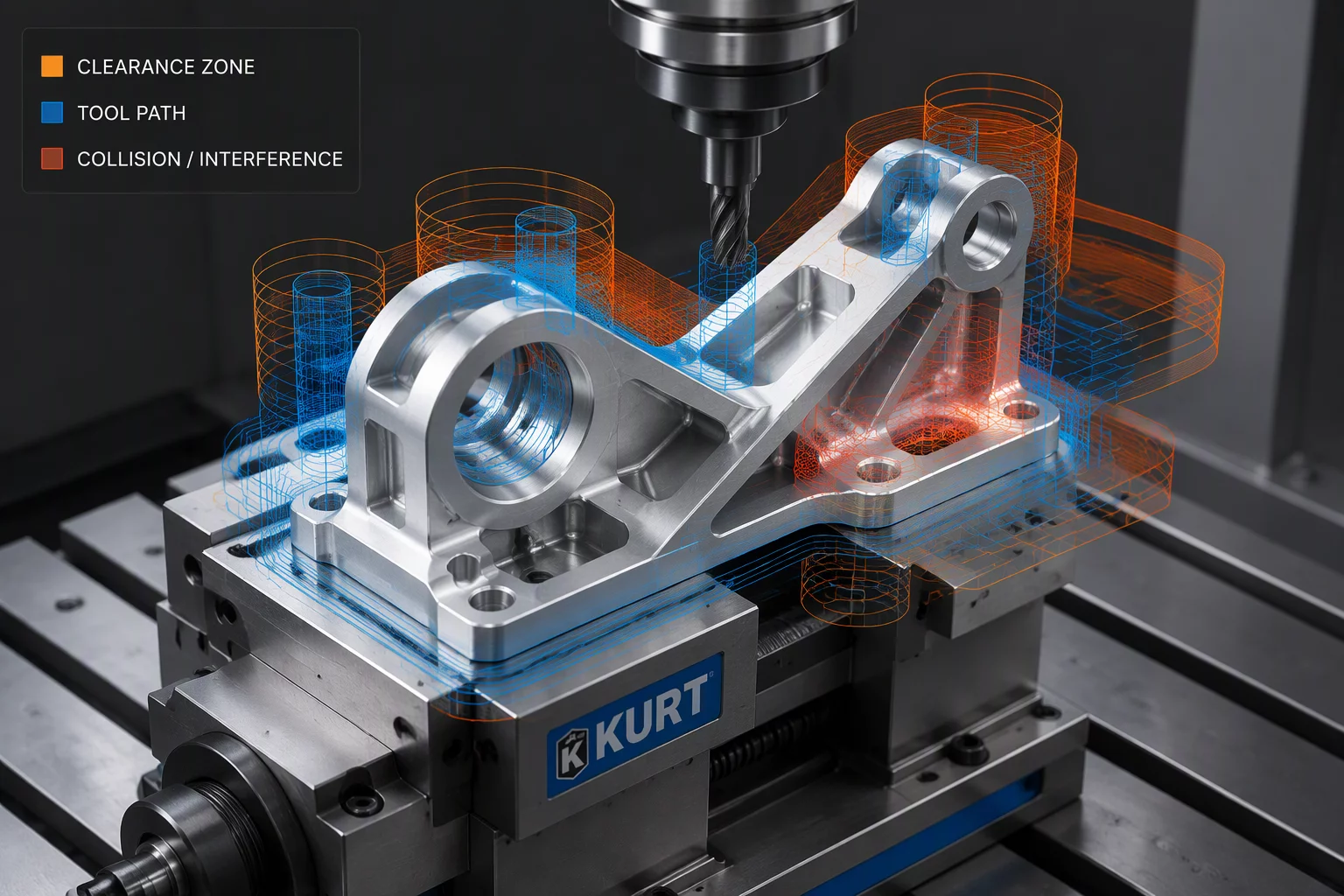
| Simulation Verification | GPU Collision Check Enabled | Validates dual-feature clearance against chuck jaws in Mastercam |
Three Steps to Isolate and Resolve Setup Competition
A methodical process to preserve geometric tolerances when two critical features battle for the same fixturing location.
Map Clamping Shadows & Tool Sweeps
Identify where fixture clamps, toe dogs, or chuck jaws physically obstruct the full approach envelope of cutting tools for both features.
Evaluate Rigidity vs. Sequence Fragility
Determine if roughing feature A removes the structural backbone needed to hold tight tolerances during the machining of feature B.
Establish an Intermediate Datum
If splitting into two setups is unavoidable, machine a high-precision datum pad in Op 10 that guarantees sub-micron alignment in Op 20.
Engineering Documentation Included in This Reference
Essential resources provided to assist CNC programmers in auditing setup interference.
Have Two Features Bottlenecking Your Machine Setups?
Submit your component geometry or fixture concept for custom operation analysis and kinematic conflict resolution.
Continue Exploring Sequence Dependencies
Compare how real-world machine shops resolve datum collisions and access trade-offs in complex workpieces.